Where do you get hot water when you are outside or in the shed? Get it heated straight from the sun with your own solar water heater! Lance Turner explains how he made a simple heater for very low cost.
There are many times when I am working in the shed that I need a small amount of hot water, such as making circuit boards, or when I want to get cleaned up before going back into the house. For these reasons, I decided to make a small solar water heater system that I could have out at the shed, thus eliminating the need to go into the house to get hot water.
The water heater is a simple design, and uses a flat panel collector connected to a plastic water tank. There is also a header tank to replace the hot water as it is used.
A lot of the material used in the project was recycled. This included both of the water tanks and the metal sheet used in the collector.
Most solar water heating systems rely on the thermosyphon effect to cause the water to flow through the panel without the aid of a pumps.
This works because as the water heats up it becomes lighter, so heavier water flows into the bottom of the panel from the bottom of the tank and pushes the hot water out of the top of the panel into the top of the tank.
There are two main requirements for this system to work. Firstly, the solar collector panel must be mounted on an incline, and secondly, the tank must be mounted above the top of the panel.
There are two different options for arranging the pipes in a solar collector panel. The first is called runner and riser, where you have a number of vertical tubes, the risers, running between two horizontal tubes, the runners. This type of collector is hard to make because it requires the tubes to be accurately drilled and soldered together.
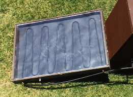
The other type, the serpentine collector, uses a single piece of pipe that winds back and forth across the collector as it rises. It is very simple and has no solder joints to fail at a later stage.
My collector used a length of 10mm outside diameter copper tube. This has an inner diameter of about 8mm, which is a bit small, but seems to work in this system. If I were to make another collector, I would use 13mm tubing.
The pipe needs to be bent about 170° at each turn, giving a five degree rise to each horizontal section of the tube. This stops any air bubbles getting trapped in the tube and stopping the thermosyphon effect. I bent my tube using a simple wooden jig that had a grooved wheel at one end and a lever arm with another grooved wheel that rolled the pipe around the first one. If this sounds to hard to make, you can get a pipe bending tool at most hardware stores, but it may cost up to $100.
Once I had bent the pipe into its serpentine shape, I soldered it onto a sheet of 0.8mm thick copper, about 850 x 450mm. I started by tacking each bend into place so that it wouldn't move as I progressed toward the top of the sheet. This took quite a while, about an hour in fact, but the finished result was a tube completely sealed to the copper sheet. The sheet did buckle a bit, but this is not really a problem, as it does not affect the ability of the collector to transfer heat to the water.
An alternative to soldering would be to use small metal straps pop-riveted over the pipe. Silicone heat conducting paste, available from electronic component stores, could be used between the pipe and sheet to improve heat transfer.
Another way of making a serpentine collector would be to use lengths of polypipe, elbow fittings and clamps to form the shape. This would then be attached to the sheet using the method above.
Once this was done, I cleaned off the excess flux, scrubbed the whole sheet with a scotchbrite pad, and painted it flat black.
The case for the collector was made from 90 x 25mm pine for the sides, and a sheet of masonite for the back. This was painted inside and out for weather protection. The glazing of the collector is a sheet of 2.5mm thick PVC plastic.
I bought this a long time ago as a cheap alternative to glass, but have since discovered how toxic it is. I would now choose the polycarbonate alternative, or better still use recycled glass.
The clear sheet was held in place with a strip of wood beading, about 15 x 20mm, also painted brown, screwed down and sealed with silicone sealant. The pipes of the collector plate were also sealed into the box with silicone.
There are two tanks used in this design, the main storage tank, which holds the heated water, and a header tank that refills the main tank as water is drawn off. Both tanks are made from HDPE (high density polyethylene) plastic drums, the type often used for water and chemical storage. One is a 20 litre drum, and the other 18 litres.
As I was not sure of the history of these drums, I cleaned them thoroughly by soaking overnight with `Excel', a biodegradable cleaner/disinfectant from Tri-nature.
The 20 litre drum was to be the main tank, but had a small hole in it that needed repairing. The box below explains how to weld HDPE plastic.
I also cut a hatch in the top of this drum, removing the original opening and most of the handle as well. I left a small amount of the handle in place so it would be easier to seal this hole by just heating the handle stub and squeezing the hole shut with a pair of pliers. However, this was not very successful, so I ended up using silicone sealant to fill the handle from inside the drum.
There are a number of ways to fit water inlets and outlets to these drums, but I made my own using a 13mm bolt drilled hollow along its length with a 8mm drill bit. I drilled a few millimetres into the head of the bolt with a 10mm drill so that I could push a short length of copper tube into it. This was then soldered into place. It should be noted here that I do not use the water from this system as potable water, so the use of lead solder and second-hand drums is acceptable, but if I had wanted to drink the water, I would have used silver solder and new materials.
I made two of these adapters, and then drilled two 13mm holes into the drum, one near the bottom and one near the top. I then fitted an O-ring to each adapter, inserted them into each hole in the drum, and fitted a large washer and brass nut to the back, tightening them enough to seal, but not enough to crush the O-rings too much.
The second tank, the header tank, does not need to be sealed, and also only needs one water outlet, at the bottom. This was done by drilling a 13mm hole in the drum and forcing a piece of polypipe into it and sealing it with silicone sealant.
I made a wooden box for the main tank from 18mm chipboard, making it big enough to fit about 40mm of insulation between the tank and the inside of the box. Two holes were also cut for the inlet and outlet.
The box was given three coats of paint to seal it against the weather and any spills. This is very important, as chipboard is easily damaged by water, swelling and disintegrating quite quickly.
The access hole in the top of the tank was sealed with a sheet of plastic cut to shape, screwed into place and sealed with silicone. Two 35mm thick bearers were mounted inside the tank box for the tank to sit on, and the tank was sealed inside the box. I didn't use insulation but I may add this later to improve performance in winter.
I made a frame out of 42 x 35mm pine from the local hardware store. This consisted of eight 400mm lengths assembled into a base similar in shape to a stool or tiny table. I used 6mm diameter x 100mm long coach bolts to hold it all together.
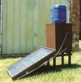
From the legs of the base ran two horizontal lengths of the same material. This increased the base size enormously and allowed me to attach the collector to the frame at about a 30° angle, making it all one unit. The tank box mounts on top of the frame, with the header tank sitting on top of the box (see figure 1).
The tank was connected to the collector using 13mm polypipe and fittings. As the outlets from the tank and collector were 10mm pipe, I had to slide some 25mm lengths of clear plastic tube over them so the polypipe would be a snug fit. Use petroleum jelly on the fittings if they feel too tight. You will need to do this to the tank before you assemble it into its box!
The inlet and outlet on the tank both had a short length of polypipe attached, just long enough to bring it outside the box, and a T-fitting was inserted into each of these. The connections were then made using polypipe as follows:
The bottom outlet was connected to the bottom inlet of the collector panel, and also to the outlet of the header tank. This allows the main tank to fill with cold water from the bottom. The top tank connections went to the top of the collector panel, and also to a plastic tap mounted on the back of the frame.
All of the connections had a crimp-on hose clamp fitted so that they couldn't be pulled off. All right angles were achieved using polypipe angle connectors, as you can't bend polypipe very far without it kinking.
That is about all there was to it. The header tank was filled with water, and refilled until the main tank had filled. I then gently rocked the whole unit lightly to allow any trapped air to escape.
On the first day of testing, which was partly overcast and reached 24°C, I got over ten litres of warm to hot water from the system, despite only setting it up at about 11am. This is more than enough water for my uses, and on sunny summer days there is plenty of very hot water. Hot enough to scald, in fact, so be careful!
On cold, cloudy days, the performance of the heater is not so good, barely heating the water to body temperature. There are a couple of ways that performance could be improved on cloudy days, including insulating the tank and the hot water pipe from the top of the panel to the tank, as this probably radiates a reasonable amount of heat.
Fixing a damaged water tankThe HDPE plastic drum that I used for the main water tank had a small hole in one side, fairly close to the bottom. While I could have attempted to seal it with silicone sealant, I have had little success in the past in repairing HDPE with any type of sealer-they just won't stick!What was needed was a way of sealing the hole so that it wouldn't fail, so I decided to have a go at plastic welding instead. Using a blowtorch on a very low setting, I gently heated the damaged area. I then placed a small piece of scrap plastic over the hole and blended it into the surrounding plastic of the drum using a heated stainless steel spatula. I also placed an aluminium plate on the other side of the hole while I was doing the repair, to stop the plastic from distorting and pushing in while the heat was applied. I found this method quite easy, once I realised that I needed to be patient. If you get the plastic too hot it will collapse or start to burn. It is just a matter of working at it slowly, and you should end up with a strong, watertight repair. |